

Volvo Penta Engine Fault Codes – Complete Reference Guide and Error Code Meanings

A practical guide to Volvo Penta engine fault codes, from flash codes to MID, PID, SPN, and FMI identifiers. Find common code meanings, possible causes, and diagnostic checks to help narrow down the problem before replacing parts.
Volvo Penta Engine Fault Codes – Complete Reference Guide and Error Code Meanings
What Are Volvo Penta Engine Fault Codes?
Volvo Penta engine fault codes are diagnosed as diagnostic trouble codes (DTCs) from the Engine Control Unit (ECU) when situations arise resulting in system malfunctions. These codes are the foundation of the onboard diagnostic system. They provide information to the technician as to why the engine runs poorly, shows poor reliability, and increases the fuel consumption and harmful emissions.
Depending on the engine model and its electronic control system, some of the most common failure codes can be a result of:
Fuel delivery and injection systems
Lubrication and oil pressure
Cooling system performance
Turbocharger and boost pressure
Air intake and exhaust systems
Emissions control components (DPF, SCR, NOx sensors where equipped)
Electrical circuits and sensor wiring
CAN bus communication
Engine speed and timing sensors
Battery charging and power supply
The primary purpose of a fault code is to identify where the engine management system has detected an abnormal condition. A fault code should not be interpreted as a failed component by default.
For example, a low fuel pressure code may be caused by:
a clogged fuel filter,
a failing fuel pump,
restricted fuel lines,
leaking injectors,
a faulty pressure sensor,
damaged wiring,
or even poor fuel quality.
Likewise, a turbocharger-related code may originate from a boost leak, sticking actuator, damaged pressure sensor, restricted air filter, or an actual mechanical turbocharger failure.
For this reason, experienced technicians always combine stored fault codes with:
live diagnostic data,
electrical measurements,
mechanical inspection,
manufacturer troubleshooting procedures,
and service documentation
before replacing any parts.
An Important Note About "Complete" Volvo Penta Fault Code Lists
Many websites claim to provide a "complete list" of Volvo Penta fault codes. In reality, no single publicly available document contains every diagnostic code used across all Volvo Penta engines.
Unlike passenger vehicle manufacturers that often publish extensive OBD-II documentation, Volvo Penta supports a wide range of marine, industrial, construction, and power-generation engines developed over many years. Different engine families use different generations of electronic control systems, and each system contains its own diagnostic database.
Fault codes vary depending on factors such as:
Engine family
Engine generation
Electronic control system
Software version
Application (marine or industrial)
Emissions certification
Examples include:
EDC15
EDC17
EMS
EVC-C
EVC-E
Mechanical engines with electronic monitoring
Modern Common Rail diesel engines
Gasoline EVC systems
Because of these differences, the same parameter may appear under different identifiers on different engines, while some proprietary Volvo Penta codes exist only for specific applications.
The definitive and continuously updated fault-code database is contained within Volvo Penta VODIA, the official factory diagnostic software used by authorized Volvo Penta service centers.
This guide is therefore not an official Volvo Penta code register. Instead, it combines information from:
Volvo Penta workshop documentation
Official service literature
Verified service manuals
SAE J1939 and J1587 diagnostic standards
Technician-verified field experience
Confirmed diagnostic reports
Only fault codes that have been documented or consistently verified have been included. Unverified or speculative code definitions have intentionally been excluded to improve technical accuracy.
Understanding Volvo Penta Diagnostic Systems
One reason Volvo Penta fault codes can appear confusing is that different generations of engines use different diagnostic architectures.
Older electronically controlled engines use flash codes to display errors. Newer engines use standardized electronic communications to display errors through the SAE J1587 or SAE J1939 communication networks.
As a result, the same engine problem may be represented differently depending on the engine generation and the diagnostic equipment being used.
Generally, Volvo Penta engines fall into two categories:
Legacy Flash Code Systems
Earlier EDC and EVC systems may display faults as flashing sequences on the diagnostic lamp or instrument panel.
Instead of showing a long electronic identifier, these systems present a simple code such as:
3.1
6.1
6.6
6.9
7.7
8.3
8.6
These flash codes correspond to specific engine faults documented in Volvo Penta workshop manuals.
Although they remain common on older engines, they provide less diagnostic detail than modern electronic fault codes.
SAE J1587 / SAE J1939 Diagnostic Systems
Most modern Volvo Penta diesel engines use standardized electronic diagnostic protocols based on SAE J1587 and SAE J1939.
Instead of a simple flash code, the diagnostic system reports multiple identifiers describing:
Which control module detected the problem
Which component or parameter is affected
What type of failure occurred
A complete fault code typically consists of several elements.
Identifier | Meaning | Purpose |
MID | Module Identifier | Identifies which electronic control module generated the fault |
PID | Parameter Identifier | Standard SAE operating parameter |
PPID | Proprietary Parameter Identifier | Volvo-specific operating parameter |
SID | Subsystem Identifier | Standard subsystem or component |
PSID | Proprietary Subsystem Identifier | Volvo-specific subsystem |
SPN | Suspect Parameter Number | J1939 parameter identifier replacing many PID values |
FMI | Failure Mode Identifier | Describes how the fault occurred |
Not every diagnostic message contains every identifier. Depending on the engine generation and scan tool, a code may include MID and PID, MID and PSID, or SPN together with FMI.
How to Read a Volvo Penta Fault Code
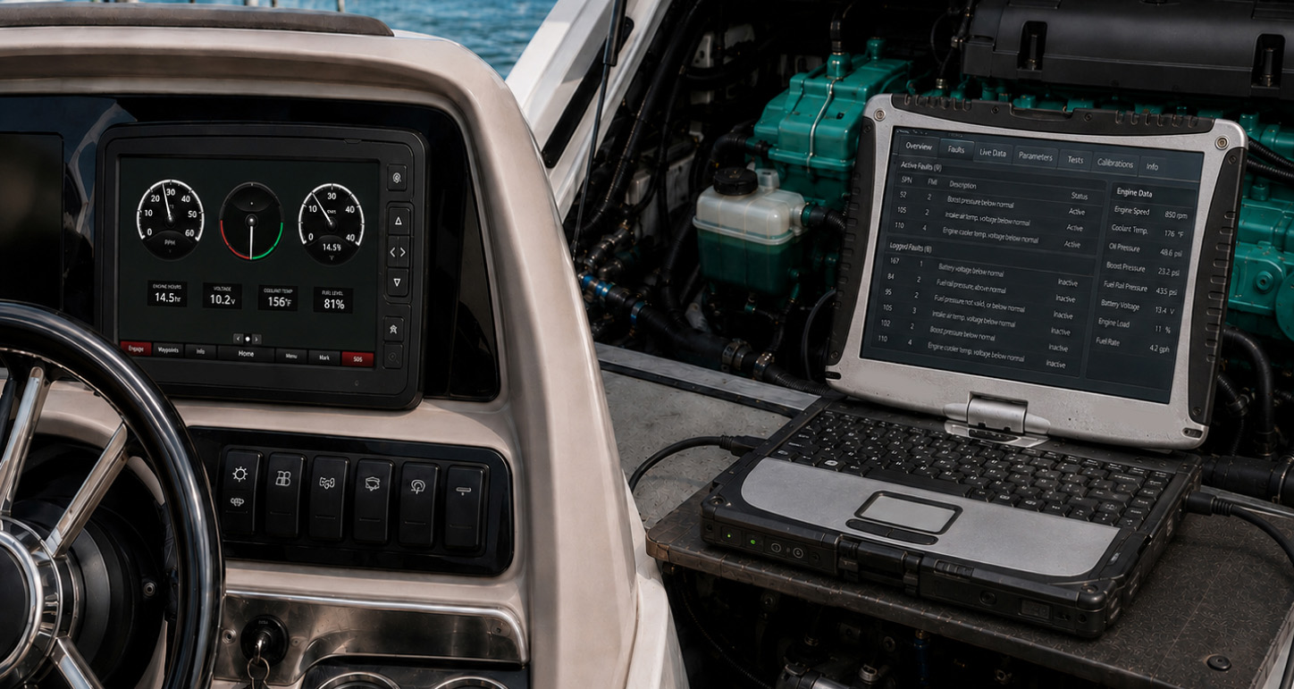
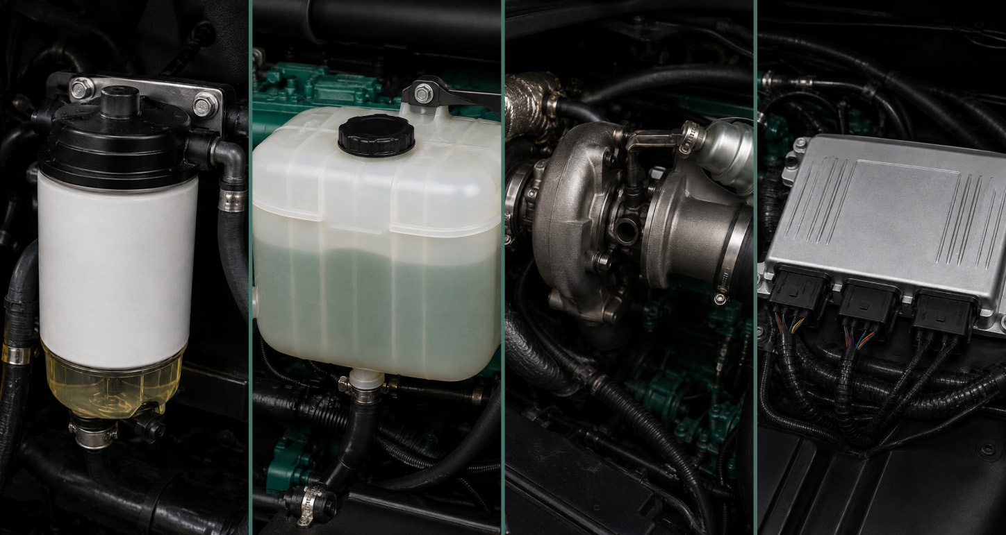
Understanding the structure of a diagnostic code allows technicians to narrow down a problem much more efficiently.
Assume this diagnostic code for example:
MID 128 SID 231 FMI 9
This code can be interpreted as follows:
MID 128 identifies the Engine Control Module (ECM).
SID 231 refers to the subsystem where the malfunction was found.
FMI 9 indicates that the communication update rate is not a normal.
Here is the another example:
MID 187 PID 127 FMI 3
This code can be broken down into:
MID 187 – Engine/EVC control module.
PID 127 – Atmospheric pressure sensor.
FMI 3 – Signal voltage above normal or an open circuit.
Rather than immediately replacing the sensor, a technician would normally inspect:
connector condition,
damaged wiring,
corrosion,
sensor power supply,
reference voltage,
and continuity
before determining whether the sensor itself has failed.
This illustrates one of the most important principles of engine diagnostics:
A fault code identifies the system in which the ECU has detected an abnormal condition. It does not automatically identify the component that must be replaced.
Why Fault Codes Should Never Be Diagnosed in Isolation
Although fault codes significantly reduce troubleshooting time, they represent only one part of the diagnostic process.
Professional diagnosis typically combines:
Stored fault codes
Active fault codes
Live sensor data
Freeze-frame information (where available)
Electrical testing
Mechanical inspection
Manufacturer service procedures
Engine operating symptoms
For example, a low boost pressure code may ultimately be caused by a split charge-air hose rather than a faulty turbocharger. Low engine oil, blocked oil passages, worn bearings, faulty oil pumps, and a failed pressure sensor are other possible causes of the oil pressure light.
Diagnosis of a fault will usually require more than simply using the fault code to replace components.This will result in higher costs and unnecessary repairs.
Understanding FMI (Failure Mode Identifier)
One of the most important parts of any Volvo Penta diagnostic trouble code is the Failure Mode Identifier (FMI). While the MID, PID, SID, PSID, or SPN identifies where the problem has been detected, the FMI explains how the fault has occurred.
For example, two diagnostic codes may reference the same sensor but indicate completely different failures. One code may indicate an open circuit, while another may indicate a short to ground or a suspicious signal. With an understanding of the FMI, technicians are able to distinguish among electrical, mechanical, calibration, and communication problems before corrective action is taken.
For modern Volvo Penta engines, FMI values are defined as per SAE J1939. These standardized definitions are commonly used in heavy-duty diesel engines and marine applications.Older J1587-based systems generally use the same meanings for the most common FMI values, although there are some implementation differences between generations. For this reason, flash codes or legacy J1587 codes should not always be cross-referenced directly with modern J1939 fault code tables.
The table below summarizes the FMI values most commonly encountered on Volvo Penta engines.
Volvo Penta FMI Codes Explained
FMI | Meaning | Typical Interpretation |
0 | Data valid but above normal operating range | A parameter that is being monitored has surpassed its normal operating limit, and the sensor is working correctly. |
1 | Data valid but below normal operating range | The measured value is lower than expected but still considered valid. |
2 | Data erratic, intermittent, or incorrect | Signal quality may fluctuate or be poor due to loose connectors, bad wiring or defective sensors. Signal quality may also be inconsistent and fluctuate. |
3 | Voltage above normal or shorted to a high source | Generally shows high circuit voltage, an open circuit, and/or signal reference loss. |
4 | Voltage below normal or shorted to ground | Insufficient voltage is indicated by faulty wiring, grounded circuits, or failures of the internal sensors. |
5 | Current below normal or open circuit | The ECU detects insufficient current flow, typically caused by an open circuit, broken wire, or disconnected component. |
6 | Current above normal or grounded circuit | Higher-than-expected current draw, often associated with short circuits or failed electrical components. |
7 | Mechanical system not responding or out of adjustment | The commanded mechanical component did not move or respond as the system expected. Common examples include turbo actuators, EGR valves, and throttle mechanisms. |
8 | Abnormal frequency, pulse width, or period | Operating range of signals passed. Most generally associated with speed sensors or pulse producing devices. |
9 | Abnormal update rate | Slow or missing communications are often indicative of CAN bus communication problems. |
10 | Abnormal rate of change | If the real-time measured value changes rapidly or slowly compared to the real situation, an implausible value of the sensor will be indicated. |
11 | Root cause unknown | The ECU detected a fault but could not determine its exact origin. Additional diagnosis is required. |
12 | Bad intelligent device or component | Failure within an electronically controlled device such as a smart sensor or control module. |
13 | Out of calibration | The sensor or actuator requires calibration or adaptation after installation or service. |
14 | Manufacturer-defined special instruction | Volvo Penta commonly uses this FMI for specific proprietary conditions. On many applications it indicates a signal shorted to ground, although the exact meaning depends on the engine family. |
17 | Data valid but below normal operating range (least severe level) | Parameter is slightly below specification but has not yet reached a critical condition. |
18 | Data valid but above normal operating range (least severe level) | Parameter is slightly above specification while remaining within a non-critical operating range. |
19 | Received network data in error | Invalid information received over the CAN network from another electronic control module. |
31 | Condition exists | The ECU has detected a specific operating condition without identifying a traditional electrical or mechanical failure. Manufacturer-specific interpretation may apply. |
How FMI Helps Narrow Down a Fault
The Failure Mode Identifier is often the key to determining whether a problem is electrical, mechanical, or communication-related.
Review the following examples:
Example 1
MID 187 PID 127 FMI 3
MID 187 identifies the engine or EVC control module.
PID 127 identifies the atmospheric pressure sensor.
FMI 3 indicates that the sensor signal voltage is higher than expected or that the circuit may be open.
Rather than replacing the sensor immediately, a technician should inspect:
damaged wiring,
loose connectors,
corrosion,
broken terminals,
poor ground connections,
and sensor supply voltage.
Example 2
MID 128 PID 94 FMI 1
MID 128 identifies the Engine Control Module.
PID 94 refers to fuel pressure.
FMI 1 means that fuel pressure is below the optimum operating range.
Possible causes may include:
clogged fuel filters,
air entering the fuel system,
restricted fuel lines,
failing fuel pump,
injector leakage,
faulty pressure sensor.
As before, the fault code points to the faulty system but does not indicate a failed component.
Example 3
MID 128 SID 231 FMI 9
Here, the ECU reports an abnormal communication update rate.
Rather than inspecting the sensor itself, diagnosis should focus on:
CAN bus wiring,
network connectors,
control module communication,
power supply stability,
terminating resistors,
software synchronization issues.
This illustrates why the FMI is just as important as the parameter identifier itself.
Common FMI Groups
Although every diagnostic code should be interpreted individually, most Volvo Penta fault codes fall into one of several general categories.
Electrical Faults
These are among the most common diagnostic events and typically involve:
FMI 3
FMI 4
FMI 5
FMI 6
Electrical faults usually result from damaged wiring, poor connector contact, corrosion, open circuits, short circuits, or failed sensors.
Mechanical Faults
Mechanical problems most commonly generate:
FMI 7
FMI 10
The examples include:
sticking turbocharger actuators,
seized EGR valves,
mechanical linkage problems,
restricted airflow,
excessive engine wear.
Communication Faults
Problems in electronic communication usually show up as:
FMI 9
FMI 19
These faults are commonly associated with:
damaged CAN bus wiring,
poor network connections,
faulty control modules,
intermittent communication between ECUs.
Sensor Performance Issues
Sensor-related diagnostic events frequently include:
FMI 0
FMI 1
FMI 2
FMI 17
FMI 18
Unlike wiring failures, these codes often indicate that the sensor is functioning correctly but is reporting operating values outside the expected range due to an actual engine condition.
Practical Diagnostic Advice
Although the FMI provides valuable information about the type of failure, it should never be interpreted in isolation. A single failure mode may have multiple possible causes depending on the engine model and operating conditions.
For example, an FMI 3 fault does not automatically mean the sensor has failed. In many cases, the root cause is damaged wiring, poor connector contact, corrosion, or a loss of reference voltage.
Likewise, an FMI 1 fault indicates that a measured value is below specification, but this may result from a genuine mechanical problem rather than an electrical fault. Low fuel pressure, for example, can be caused by a clogged filter, a failing fuel pump, injector leakage, or restrictions within the fuel system.
Professional diagnosis should always combine fault codes with live diagnostic data, electrical testing, mechanical inspection, and the troubleshooting procedures specified in the Volvo Penta workshop manual.
Volvo Penta Engine Fault Codes by System
The following reference combines fault codes documented in Volvo Penta workshop literature, SAE diagnostic standards, and widely verified field reports. Because Volvo Penta uses multiple generations of engine management systems, not every code applies to every engine family.
Some engines display legacy flash codes (such as 6.1 or 8.3), while newer systems report diagnostic information using MID/PID/SPN/FMI or MID/PSID/FMI identifiers. Both formats are included where appropriate.
Engine Lubrication System
The lubrication system is continuously monitored because insufficient oil pressure can rapidly lead to severe engine damage. Depending on the engine generation, the ECU may monitor both oil pressure and the electrical integrity of the oil pressure sensor.
Fault Code | Parameter | Description | Possible Causes |
3.1 / PID 100 | Oil Pressure Sensor | Sensor circuit fault | Open circuit, short circuit, damaged wiring, faulty sensor |
6.6 / PID/SPN 100 | Engine Oil Pressure | Oil pressure below specification | Low oil level, worn oil pump, clogged pickup, worn bearings, incorrect oil viscosity |
MID 128 PID 100 FMI 1 | Oil Pressure | Low engine oil pressure | Low oil level, oil pump failure, pressure sensor fault |
MID 128 PID 175 FMI 4 | Oil Temperature Sensor | Sensor voltage below normal | Wiring fault, connector corrosion, sensor failure |
Cooling System
The cooling system protects the engine from overheating and continuously monitors coolant temperature and coolant-related operating parameters.
Fault Code | Parameter | Description | Possible Causes |
6.1 / PID/SPN 110 | Coolant Temperature | Engine coolant temperature too high | Low coolant level, thermostat failure, blocked radiator, failed water pump |
6.7 / PPID 8 / SPN 520192 | Piston Cooling Pressure | Cooling oil pressure too low | Lubrication restriction, oil pump problems |
MID 128 PID 110 FMI 0 | Coolant Temperature | Coolant temperature above normal | Cooling system malfunction |
MID 128 PID 171 FMI 3 | Ambient Air Temperature | Voltage above normal | Damaged sensor, wiring fault |
MID 128 PID 172 FMI 4 | Intake Air Temperature | Voltage below normal | Failed sensor, poor electrical connection |
A high coolant temperature fault should never be ignored. Many Volvo Penta engines automatically reduce engine power to protect internal components and may eventually initiate engine shutdown if overheating continues.
Fuel System and Injection
Fuel delivery faults are among the most common diagnostic events on electronically controlled Volvo Penta engines. Modern ECUs monitor fuel pressure, injection pressure, injector driver circuits, and pressure control valves.
Fault Code | Parameter | Description | Possible Causes |
8.3 / PID/SPN 164 | Injection Pressure | Injection pressure fault | Fuel pump failure, restriction, sensor fault |
8.3 / PSID 97 / SPN 679 | Pressure Valve | Pressure regulating valve malfunction | Valve leakage, valve stuck open or closed |
MID 128 PID 94 FMI 1 | Fuel Pressure | Fuel pressure below specification | Plugged filter, weak fuel pump, injector leakage |
MID 187 PSID 17 FMI 14 | Fuel Pressure Sensor | Signal short to ground / manufacturer-defined fault | Wiring or sensor failure |
MID 128 PID 174 FMI 3 | Fuel Temperature | Voltage above normal | Sensor failure or damaged wiring |
SPN 392960 FMI 17 | Injector Driver Circuit | Injector driver performance issue | ECM driver, injector wiring |
SPN 524032 FMI 17 | Injector Driver Circuit – Cylinder 4 | Cylinder-specific injector driver fault | Wiring, injector, ECM output |
When diagnosing low fuel pressure faults, technicians should inspect the entire fuel supply system before replacing electronic components. Contaminated fuel, clogged filters, air leaks, and injector problems lead to the same diagnostic code.
Air Intake and Turbocharging
The intake system relies on multiple sensors to calculate fuel delivery and turbocharger performance. Faults in these systems often result in reduced engine power, poor acceleration, increased fuel consumption, or excessive exhaust smoke.
Fault Code | Parameter | Description | Possible Causes |
MID 187 PID 127 FMI 3 | Atmospheric Pressure Sensor | Signal voltage above normal | Open circuit, sensor fault |
MID 187 PID 177 FMI 3 | Intake Manifold Pressure | Voltage above normal | Wiring fault, intake leak, turbocharger issue |
MID 128 PID 245 FMI 0 | Boost Pressure | Boost pressure above normal | Turbocharger control fault, sticking VGT, sensor error |
Before replacing the turbocharger, technicians should inspect:
intake hoses,
charge-air cooler,
intercooler connections,
air filter restriction,
boost pressure sensor,
turbo actuator operation,
intake manifold leaks.
Many boost-related fault codes ultimately result from relatively simple air leaks rather than mechanical turbocharger failure.
Engine Speed and Position Sensors
Accurate engine speed information is critical for injection timing, synchronization, and engine management.
Fault Code | Parameter | Description | Possible Causes |
MID 128 PID 190 FMI 2 | Engine Speed | Engine speed signal intermittent | Crankshaft position sensor, damaged wiring, excessive sensor gap |
Intermittent engine speed faults frequently produce difficult-to-diagnose symptoms such as:
intermittent engine shutdown,
extended cranking,
unstable idle,
loss of synchronization,
unexpected engine derate.
Electrical System
Electronic engine management depends on a stable electrical supply. Battery voltage problems may generate numerous secondary fault codes throughout the control system.
Fault Code | Parameter | Description | Possible Causes |
6.9 / PID/SPN 158 | Battery Voltage | Battery voltage abnormal | Weak battery, alternator failure, poor cable connections |
8.6 / SID 70 / SPN 729 | Preheating System | Preheater circuit fault | Relay failure, damaged wiring harness, glow system fault |
Low system voltage can produce misleading sensor faults. For this reason, battery condition and charging voltage should always be verified before diagnosing multiple unrelated electrical codes.
Accelerator and Engine Controls
The ECU continuously monitors driver input devices such as the accelerator pedal and throttle position sensors.
Fault Code | Parameter | Description | Possible Causes |
MID 128 PID 84 FMI 2 | Accelerator Pedal Position | Signal erratic | Pedal sensor, damaged connector, wiring |
MID 128 PID 91 FMI 3 | Throttle Position | Voltage above normal | Sensor failure, electrical fault |
These faults may cause:
reduced engine response,
unstable throttle operation,
limp-home mode,
engine derate.
Emissions Control Systems
Emission-related diagnostics vary considerably depending on engine generation and emissions certification. Engines equipped with modern aftertreatment systems may monitor oxygen sensors, NOx sensors, DPF differential pressure, DEF dosing, and SCR performance.
Fault Code | Parameter | Description | Possible Causes |
SPN 4239 FMI 0 | Long-Term Fuel Trim (Bank 2) | Fuel trim above normal | Oxygen sensor issues, fuel system imbalance |
Some Volvo Penta applications also monitor:
NOx sensors,
exhaust gas temperature sensors,
SCR efficiency,
DEF dosing,
DPF differential pressure,
regeneration performance.
Because these systems differ significantly between engine families, emissions-related fault codes should always be verified against the workshop manual for the specific engine model.
Fault Codes Most Frequently Encountered in the Field
Although Volvo Penta engines support hundreds of diagnostic codes, service technicians consistently report that a relatively small group accounts for the majority of troubleshooting cases.
The most common fault categories include:
Low fuel pressure
High coolant temperature
Low engine oil pressure
Turbocharger boost pressure faults
Intake pressure sensor faults
Crankshaft position sensor faults
Battery voltage problems
CAN bus communication faults
Injector driver circuit faults
DPF differential pressure faults (where equipped)
SCR and DEF system faults (where equipped)
Sensor voltage high or low
Intermittent communication errors
These recurring faults are often caused by basic mechanical or electrical issues such as clogged filters, damaged wiring, poor connector contact, corroded terminals, air leaks, low fluid levels, or inadequate system maintenance rather than failure of expensive electronic components.
Engine Sensors That Most Commonly Trigger Fault Codes
Modern Volvo Penta engines rely on dozens of electronic sensors to monitor engine operation in real time. Sensors relay information to the Engine Control Unit (ECU) constantly. Optimizations of fuel injection, timing of the engine, and the functioning of the turbo are a few examples of what the ECU is capable of doing with sensors. The ECU also takes control of the level of emissions and engine safety.
When a sensor signal is outside its operational limits or is electrically invalid, the ECU saves a Diagnostic Trouble Code (DTC). Just because a fault code is stored doesn’t mean the sensor has failed. Poor wiring, poor electrical connections, mechanical issues, abnormal conditions of operation can all result in the same fault code.
These sensors are some of the most typical sources of Volvo Penta engine fault codes.
Sensor | Typical Function | Common Symptoms |
Coolant Temperature Sensor | Monitors engine coolant temperature | Overheating warnings, engine derate |
Oil Pressure Sensor | Monitors lubrication pressure | Low oil pressure alarms, engine protection |
Fuel Pressure Sensor | Monitors fuel supply pressure | Hard starting, power loss |
Fuel Temperature Sensor | Measures fuel temperature | Fuel system performance issues |
Intake Air Temperature Sensor | Measures intake air temperature | Reduced power, poor combustion |
Boost Pressure Sensor | Measures turbocharger boost pressure | Loss of power, excessive smoke |
Atmospheric Pressure Sensor | Provides altitude compensation | Incorrect fueling calculations |
Crankshaft Position Sensor | Determines engine speed and crankshaft position | No-start, intermittent shutdown |
Camshaft Position Sensor | Controls injection timing | Rough running, synchronization faults |
Accelerator Pedal Position Sensor | Detects throttle input | Poor throttle response, limp mode |
Turbocharger Actuator | Controls variable turbo geometry or wastegate | Reduced boost pressure |
Exhaust Gas Temperature Sensor | Monitors exhaust temperature | Regeneration or protection faults |
NOx Sensor (where equipped) | Measures nitrogen oxide emissions | SCR system faults |
Differential Pressure Sensor | Monitors DPF restriction | Regeneration problems |
Water-in-Fuel Sensor | Detects water contamination | Fuel contamination warnings |
While these sensors are frequently associated with diagnostic codes, technicians should always verify the integrity of the wiring harness, connectors, and mechanical systems before replacing any electronic component.
The Most Common Volvo Penta Engine Problems
Although Volvo Penta ECUs are capable of reporting hundreds of different fault codes, a relatively small number of underlying problems account for most service calls.
Low Fuel Pressure
Low fuel pressure is commonly identified as a main issue, but can be caused by many things. Situations that may cause low fuel pressure include; blocked fuel filters, fuel line restrictions, fuel line air intrusions, use of a worn fuel pump, fuel injector leakage, use of contaminated fuel, and faulty pressure sensors.
Common fault codes:
MID 128 PID 94 FMI 1
8.3 / PID-SPN 164
Typical symptoms:
Hard starting
Engine hesitation
Reduced power
Poor acceleration
Engine derate
High Coolant Temperature
Overheating is another common reason for engine protection strategies to activate.
Possible causes include:
Low coolant level
Blocked radiator or heat exchanger
Thermostat failure
Water pump failure
Restricted coolant flow
Cooling fan malfunction
Common fault codes:
MID 128 PID 110 FMI 0
6.1 / PID-SPN 110
Many Volvo Penta engines automatically reduce engine power when coolant temperature exceeds safe operating limits.
Low Oil Pressure
Engine lubrication faults should always be treated as high priority because continued operation may result in severe internal engine damage.
Possible causes include:
Low engine oil level
Incorrect oil viscosity
Oil pump failure
Worn bearings
Restricted oil passages
Faulty pressure sensor
Common fault codes:
MID 128 PID 100 FMI 1
6.6 / PID-SPN 100
Turbocharger and Boost Pressure Problems
Turbocharger-related diagnostic events may originate from mechanical or electronic causes.
Common causes include:
Split charge-air hoses
Air leaks
Blocked air filters
Sticking VGT actuator
Boost pressure sensor failure
Damaged turbocharger
Typical fault code:
MID 128 PID 245 FMI 0
Sensor Communication Failures
Intermittent communication failures are more often than not due to damaged wiring rather than faulty sensors.
Typical causes:
Loose connectors
Corrosion
Damaged harness
Water intrusion
Poor grounding
Common FMI values:
FMI 2
FMI 9
FMI 19
CAN Bus Communication Errors
Today's Volvo Penta engines have multiple control modules that communicate with each other continuously.
If communication becomes unreliable, numerous unrelated fault codes may appear simultaneously.
Typical causes include:
CAN wiring damage
Connector corrosion
Failed terminating resistors
Power supply interruptions
Faulty control modules
Emissions System Faults
Engines equipped with emissions aftertreatment systems may report additional diagnostic codes related to:
DPF differential pressure
Exhaust temperature
SCR efficiency
DEF dosing
NOx sensors
Regeneration performance
Because emissions hardware differs significantly between engine families, these faults should always be interpreted using the workshop manual for the specific engine model.
Practical Troubleshooting Guide
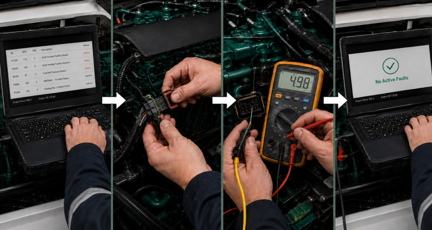
Receiving a fault code is only the beginning of the diagnostic process. Correct diagnosis requires determining whether the reported fault is electrical, mechanical, hydraulic, pneumatic, or software-related.
Experienced technicians typically follow a structured troubleshooting sequence.
Step 1 – Record the Fault Code
Before clearing any diagnostic information, log the complete code as displayed, uninterpreted.
Examples:
MID 128 PID 94 FMI 1
MID 187 PID 127 FMI 3
SPN 4239 FMI 0
Flash code 6.1
The complete identifier is essential because changing only one portion of the code may indicate an entirely different fault.
Step 2 – Determine Whether the Fault Is Active
Systems from Volvo Penta can generally be categorized as:
Active Fault
The problem currently exists.
The ECU continues detecting abnormal operating conditions.
Inactive Fault
The problem occurred previously but is no longer present.
Examples include:
temporary voltage drop
loose connector
intermittent wiring fault
transient communication error
Sometimes, diagnosing problems that only happen from time to time can be made easier by looking at inactive faults.
Step 3 – Perform a Visual Inspection
Before connecting advanced diagnostic equipment, inspect:
Wiring harnesses
Connector locking tabs
Corrosion
Bent terminals
Chafed insulation
Damaged hoses
Air leaks
Fuel leaks
Coolant level
Oil level
There are many engine faults that can be resolved during this first inspection.
Step 4 – Check Live Diagnostic Data
Stored fault codes indicate what the ECU detected, but live data reveals what is happening now.
Important parameters include:
Fuel pressure
Oil pressure
Coolant temperature
Intake pressure
Boost pressure
Battery voltage
Engine speed
Sensor voltage
Turbo actuator position
Replacing parts unnecessarily becomes less frequent once engineer experience is applied and compared live sensor values versus manufacturer’s specs.
Step 5 – Perform Electrical Testing
If the fault appears electrical, verify:
Sensor supply voltage
Ground integrity
Signal voltage
Circuit continuity
Connector resistance
Short circuits
Open circuits
Replacing sensors before performing basic electrical testing is one of the most common diagnostic mistakes.
Step 6 – Verify the Mechanical System
Not every electronic fault has an electronic cause.
Examples include:
Low fuel pressure may result from:
clogged filters,
air leaks,
weak fuel pump,
injector leakage.
Turbocharger faults may result from:
split boost hoses,
sticking actuators,
blocked air filters,
charge-air cooler leaks.
Always eliminate mechanical causes before replacing electronic components.
Using Volvo Penta VODIA
For comprehensive diagnostics, Volvo Penta recommends using VODIA (Volvo Onboard Diagnostic and Information Application), the manufacturer's official diagnostic platform.
VODIA provides functions that are not available through generic scan tools, including:
Reading active and inactive fault codes
Displaying live operating data
Clearing stored diagnostic codes
Viewing freeze-frame information (where supported)
Running guided diagnostic procedures
Performing calibrations and adaptations
Programming certain control modules
Accessing model-specific service information
Because Volvo Penta engines vary significantly between model families, VODIA remains the most reliable method for obtaining the correct fault-code description and troubleshooting procedure.
Important Diagnostic Principles
Several key principles should always be remembered when interpreting Volvo Penta fault codes:
A fault code identifies the affected system, not necessarily the failed component.
The generation and engine family, as well as operational conditions, can cause the same fault code to have many different causes.
Always diagnose wiring, connectors, and mechanical systems before replacing sensors.
Use live data together with stored fault codes whenever possible.
Verify battery voltage and the charging system before attempting to diagnose multiple, unrelated, electrical faults.
Workshop manual specific engine model number may vary in applications and proprietary Volvo Penta may use.
After repairs, clear stored codes and confirm that the fault does not return during normal engine operation.
FAQ
Can I continue operating my Volvo Penta engine with an active fault code?
It depends on the type of fault.
Some fault codes are just warnings to the driver, while some will engage engine derate, controls to limit engine speed, or even fully shut down the engine to protect it from failure. One of the more common diagnostic codes you find is low fuel pressure. This is most commonly caused by clogged fuel filters, fuel lines that are either restricted or plugged, air in the fuel system, bad fuel pumps, fuel injector leaks, contaminated fuel, or bad pressure sensors.
For example:
A temporary communication fault may have little immediate impact on engine performance.
Low oil pressure or excessive coolant temperature can trigger immediate engine protection functions and should never be ignored.
Emissions-related faults may initially illuminate a warning indicator but can eventually result in derate if the underlying problem remains unresolved.
If a warning lamp remains illuminated or the engine enters a protection mode, diagnose the fault as soon as possible before continuing normal operation.
What does MID 128 mean?
MID (Module Identifier) identifies the electronic control module that generated the fault.
MID 128 is the Engine Control Module (ECM) on many Volvo Penta applications and is the module responsible for monitoring engine performance, fuel injection, lubrication, cooling, turbocharging, and many other operating systems.
Because the ECM oversees the majority of engine functions, MID 128 is one of the most commonly encountered identifiers in Volvo Penta diagnostic systems.
What does MID 187 mean?
On many Volvo Penta engines equipped with Electronic Vessel Control (EVC), MID 187 identifies the EVC or engine interface control module.
Depending on the engine family and software version, MID 187 may report faults related to:
atmospheric pressure sensors,
intake pressure,
fuel system monitoring,
engine interface communication,
proprietary Volvo Penta functions.
Always confirm the exact module description using the workshop manual or Volvo Penta VODIA, as module assignments may differ between engine generations.
What is FMI?
FMI (Failure Mode Identifier) describes the type of fault detected by the ECU.
Instead of pointing out the affected element, the FMI describes the problem in this way:
voltage above normal,
voltage below normal,
intermittent signal,
open circuit,
short circuit,
communication error,
mechanical malfunction,
calibration issue.
Understanding the FMI is essential for narrowing the diagnostic process before replacing parts.
What is the difference between PID, SID, PSID, PPID, and SPN?
These identifiers relate to particular fault parameters or subsystems associated with the fault.
PID (Parameter Identifier) – Standard SAE operating parameter.
SPN (Suspect Parameter Number) – J1939 parameter identifier used by most modern diagnostic systems.
SID (Subsystem Identifier) – Standard subsystem or component.
PSID (Proprietary SID) – Volvo-specific subsystem identifier.
PPID (Proprietary PID) – Volvo-specific parameter identifier.
Depending on the engine generation and diagnostic protocol, a fault code may contain one or more of these identifiers.
Can fault codes be cleared?
Yes.
After the underlying problem has been repaired, active and stored diagnostic trouble codes can usually be cleared using compatible diagnostic software.
However, simply clearing the codes does not repair the fault. If the original condition still exists, the ECU will detect it again and the code will immediately return.
Volvo Penta suggests that before clear stored diagnostic information, it is important to validate if the repair was performed correctly.
Can generic scan tools read Volvo Penta fault codes?
Some generic J1939-compatible diagnostic tools can read basic engine fault codes, especially on modern electronically controlled diesel engines.
Limited access to Volvo Penta diagnostics with non-specific coding tools is to be expected.
Functions that may require Volvo Penta VODIA include:
proprietary PSID and PPID descriptions,
advanced live data,
service routines,
calibrations,
software updates,
guided troubleshooting,
control module programming.
For complete diagnostics, VODIA remains the recommended diagnostic platform.
Why does the same fault code appear on different engines?
Although Volvo Penta follows industry-standard diagnostic protocols, individual engine families may implement proprietary parameters or software differently.
Factors that influence fault code interpretation include:
engine model,
electronic control system,
software version,
emissions certification,
marine or industrial application.
For this reason, a fault code should always be verified against the workshop manual for the exact engine model.
What should I do if my fault code is not listed?
Because Volvo Penta supports many different engine families, it is impossible to include every diagnostic code in a single public reference.
If your code is not listed:
Record the complete identifier exactly as displayed.
Note the engine model and serial number.
Determine whether the fault is active or inactive.
Check the workshop manual for your specific engine.
Use Volvo Penta VODIA whenever possible.
Complete codes such as MID 128 PID 94 FMI 1, SPN 4239 FMI 0, or Flash Code 6.1 will greatly improve diagnostic accuracy.
Final Thoughts
Designed to anticipate developing mechanical breakdowns, Volvo Penta diagnostic systems simplify fault finding. Understanding how diagnostic codes are structured—and how to interpret identifiers such as MID, PID, SID, PSID, SPN, and FMI—allows technicians and equipment owners to approach faults systematically rather than relying on guesswork.
It is equally important to recognize that a fault code identifies the system where the Engine Control Unit has detected a problem, not necessarily the component that requires replacement. Electrical faults, wiring damage, poor connector contact, sensor failures, mechanical wear, and operating conditions can all produce similar diagnostic codes.
Successful diagnosis should therefore combine:
fault-code interpretation,
live diagnostic data,
electrical testing,
mechanical inspection,
manufacturer troubleshooting procedures,
and model-specific service documentation.
While this guide brings together verified information from Volvo Penta workshop literature, SAE J1939 diagnostic standards, and technician-verified field experience, it should be considered a practical reference rather than a replacement for the official workshop manual or Volvo Penta VODIA.
Using the correct diagnostic process not only reduces unnecessary parts replacement but also minimizes downtime, improves reliability, and helps ensure the long-term performance of your Volvo Penta engine.
Quick Reference Checklist
Before replacing any component, always verify the following:
✔ Record the complete fault code (MID/PID/SPN/FMI or Flash Code)
✔ Determine whether the fault is active or inactive
✔ Perform a visual inspection of wiring and connectors
✔ Check battery voltage and charging system condition
✔ Review live sensor data
✔ Inspect related mechanical components
✔ Consult the workshop manual for your engine model
✔ Clear fault codes only after repairs have been completed
✔ Confirm that the fault does not return during operation
Editor's Note
This guide combines information from Volvo Penta workshop documentation, SAE J1939/J1587 diagnostic standards, and technician-verified field experience. During the preparation of this article, we also consulted the engineering team at DrunkLab, whose specialists have extensive hands-on experience working with Volvo Penta ECUs and engine programming. Several sections were reviewed against practical service experience rather than relying solely on published documentation. Our confidence in their expertise comes from firsthand experience as well—we've even turned to them in the past to tune a boat equipped with a Volvo Penta engine, and that practical insight helped validate some of the recommendations included here.
Because Volvo Penta continuously updates engine software and diagnostic systems, fault-code definitions and diagnostic procedures may vary between engine families and software revisions. Always refer to the official workshop manual and the Volvo Penta VODIA diagnostic system when performing maintenance or repairs on a specific engine model.
By David Nelson
Independent Technical Writer
Last updated: August 04, 2026
Review
You can leave a review on the contact page.
Related Articles
Mochester App (M4 App) for Volvo Construction Equipment: Smart Diagnostics and Tuning Made Easy
Remote tuning solutions for Volvo construction machines are available through the Mochester App (M4 App). This guide outlines the App's primary functions and how to use it to enhance the performance of your machines, minimize their downtime, and better their fuel efficiency.

Volvo Construction Equipment Software: Solutions for Diagnostics and Tuning
Modern Volvo Construction Equipment depends on sophisticated electronic systems that use software for diagnostics and optimization. This article analyzes the most common tools such as Volvo Tech Tool, VCADS Pro, Jaltest, and Mochester App, and their functions regarding fault identification, ECU programming, and system calibration. Other tuning options including performance optimization as well as DPF, EGR, and SCR deletes are discussed. Overall, correct application of these tools and techniques can help minimize production downtime, enhance operational efficiency, and prolong the natural working life of Volvo CE equipment.

Volvo Construction Equipment Fault Codes List: Overview of Common Errors and Their Meanings
A practical overview of common Volvo CE fault codes, how to read them, and what they mean for diagnostics and repair.